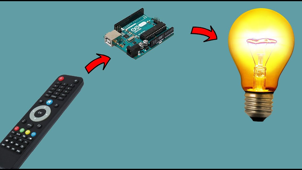
Control Bulb Using Arduino
We are using an Arduino UNO to operate the automatic street light control system. 10-15 watts are enough.

Arduino Blink Torch Bulb Video Code Circuit Diagram Arduino Circuit Diagram Coding
Output Signal from Arduino.
. Working of Arduino Lamp Dimmer Circuit. The above circuit is for Arduino to LCD connection. Adjust 10K potentiometer for adjusting LCD contrast.
An electric generator is mechanically identical to an electric motor but operates. Due to a lot of requests from my subscribers and followers on my YouTube channel Electronic Clinic to explain how to create your own android application. So I hope the knowledge in this tutorial will be useful for your creations.
There is a problem associated with the street lights that they keep on during the daytime or early in the morning when there is no need for artificial bulb light. I will show you how to do it with both relays and transistors. This was a satisfying project because I learned a lot about PID and made a practical PID temperature control device.
Safely control AC equipment using an Arduino. Using a low frequency pulse width modulation turns a bang-bang controlled heating element into a fully modulated element. To my joy flashing and variable intensity was observed.
A few quick points. This tutorial is based on IoT and covers how to control a servo motor using ESP8266 and the Blynk app. Low dimming step 2.
We will be using a 26W light bulb. Here we have used an LED bulb as output. PhaseAngle Control Using Triac 3.
I then weighed the white spool of wire and each of the other spools. Which in actual life measured more like 35 VAC and a 28-volt incandescent light bulb Mouser Digikey have these. Full tutorial can be found here.
A Working Video and Arduino Light Dimmer Code is given. For example - you may have button on V1 that controls wi-fi bulb A and another button on V1 that controls wi-fi bulb B. In this tutorial.
How to control arduino Wirelessly with blynk via USB. For this experiment any load and any low voltage will work. Auf dieser Seite finden Sie alle Informationen der Deutschen Rentenversicherung die jetzt wichtig sind.
Beratung und Erreichbarkeit Online-Antragstellung Servicetipps und vieles mehr. Simple instruction to let you know how to control an AC voltage device using an IR remote control and the Arduino. This circuit is very simple circuit with a LDR sensor module and Arduino UNO.
12 V LED with Arduino. The Arduino Code for changing delay in mS. Once I have uploaded the code.
This driver board mainly includes PCA9685 PWM driver IC. Breadboard drawing of an Arduino Uno on the left connected to a solderless breadboard on the right. If you already know the basics of Python then youll be able to get started with Arduino by using Python to control it.
This is how an AC Light Dimmer circuit can be built easily using TRIAC and optocoupler. That is we can control 16 servo motors using the SCL and SDA pins on the Arduino board. In this project we are going to make a Simple AutomaticLight Controller using LDR.
Figure 11 shows an Arduino Uno on the left connected to a solderless breadboard right. Also we can connect this driver board to the Arduino board using the I2C communication. The picture above shows the completed circuit for the remote control light bulb using the relay.
The white spool had a weight of 353 grams. First a 100W light bulb then a desk lamp and a fan heater. Learn how to use Relays and Solid State Switches to build a light-activated relay and a marquis light chaser.
This is much better than a light bulb. Arduino arduino There is a demonstration of this example at the end of the video of this tutorial. There are 3 push buttons for setting temperature and humidity.
The DHT11 sensor is connected to pin A0. IR Remote Control and Arduino Control AC. In our path towards modernization automation plays an important role.
If you want to control more than that you can continue to connect the driver board as a chain. The last thing to check is to make sure the relay is rated for the load in this case the light bulb. Also the servo motor can be considered an essential component in robot design.
Zero Cross Detector Circuit. This tutorial will show you how to control the higher voltage devices eg. On the Arduino module use the 5V or 33V depending on your model and any of the ground connections as shown in Figures 11 and 12.
So using my tape measure and scale I believe that the wire in the package I received exceeds the length in the description. Some applications of this circuit are street light controlling homeoffice light controlling day and night indicators etc. Our experiment will involve using an Arduino to control a 5-meter strip of RGB.
Coronavirus - Service und Informationen Die Corona-Pandemie bedeutet drastische Einschnitte in allen Lebensbereichen. Control Arduino with Blynk over USB. The 22k resistor limits the current into the base of the transistor while the 10k resistor is a pull-up resistor for the switch.
Below are the pictures of showing three stages of dimming the AC bulb using Arduino and TRIAC. Medium Dimming step 3. When using 2 Arduino UNO with Ethernet shields flashing default example to both of them will cause.
Android app development So far I have been using Android applications to control Arduino over BluetoothI will share the links of all the projects in which I have used the android applications. Home automation enables us to control any electrical appliances like fan TV lights AC from any place in the world. The Arduino IDE and libraries made programming and testing a breeze.
The definitive test was switching a 120V resistive load 60W light bulb. I hope you will find it useful. So thats how we can control any High Voltage Device using Arduino or actually any other microcontroller.
Nodemcu ESP8266 board and Blynk application are mainly used for this tutorial. That means the relay electromagnet is directly powered from the Arduinos power pin. The remaining four spools had a weight of 355 359 368 and 368 grams.
At 120VAC this give us 26W120Vac 216A. Note that in addition to the Arduino TIP120 light bulb and battery youll need a pushbutton switch and a couple of resistors. As heating element I highly recommend Kanthal wire used for styrofoam cutting.
All of these devices work on 220V. The duty cycle of the heater is determined by the temperature PID loop. The frequency is usually between 50 60 HZ.
The AC voltage that we get from home supply is around 310 volts peak to peak or 220V RMS. Arduino 4 - Anode of the yellow LED shorter pin of the yellow LED Arduino 5 - Anode of the red LED shorter pin of the red LED Arduino GND - Cathode of all LEDs via a 220 ohm resistor longer pin of the LEDs You can find the code corresponding to this circuit in the attached file or on my Arduino web editor at ir-led-control. 100W incandescent light bulb as a load.
The Arduino is the brain of the project. Without the jumper cap you need to provide a separate power source to power up the relays electromagnet through the JD-VCC pin. An electric motor is an electrical machine that converts electrical energy into mechanical energyMost electric motors operate through the interaction between the motors magnetic field and electric current in a wire winding to generate force in the form of torque applied on the motors shaft.
I measured the output SPWM signal from the two pins of the Arduino which looks like the below image If we zoom in a little bit we can see the ever-changing duty cycle of the PWM wave. I tested 3 devices on it. The pin A5 controls the relay for vaporizer and A4 for the bulb.
The Arduino platform includes both hardware and software products. All in all Arduino and Python can facilitate an effective learning environment that encourages developers to get into electronics design. Potentiometer Part to Control the Dimming 4.
Pin On Fair Electro

Light A Bulb With Arduino Ultrasonic Sensor Hc Sr04 Arduino Arduino Projects Arduino Projects Diy

Ir Remote Control Project For Automation Arduino Arduino Circuit Engineering Projects

Arduino Light Sensor Circuit Using Ldr Arduino Light Sensor Light Sensor Circuit Light Sensor

Arduino Temperature Dependent Light Bulb With 5v Relay Arduino Circuit Arduino Circuit Basics

Blink Ac Bulb With Arduino Relay Module Arduino Arduino Projects Diy Arduino Projects
0 Response to "Control Bulb Using Arduino"
Post a Comment